
Calculator guide
Beam design calculator to Eurocode 2: rectangular, T and L beams
Design a reinforced concrete beam to EN 1992-1-1 with the free calculator: spans and sections, loads, bending, links, deflection and cracking.
- Reading time
- 4 minutes
- Standard
- EN 1992-1-1
- Clauses
- 5.3.2, 6.1, 6.2, 7.3.3, 7.4.2, 9.2
- Calculator
- Beam
- Updated
On this page 7 sections
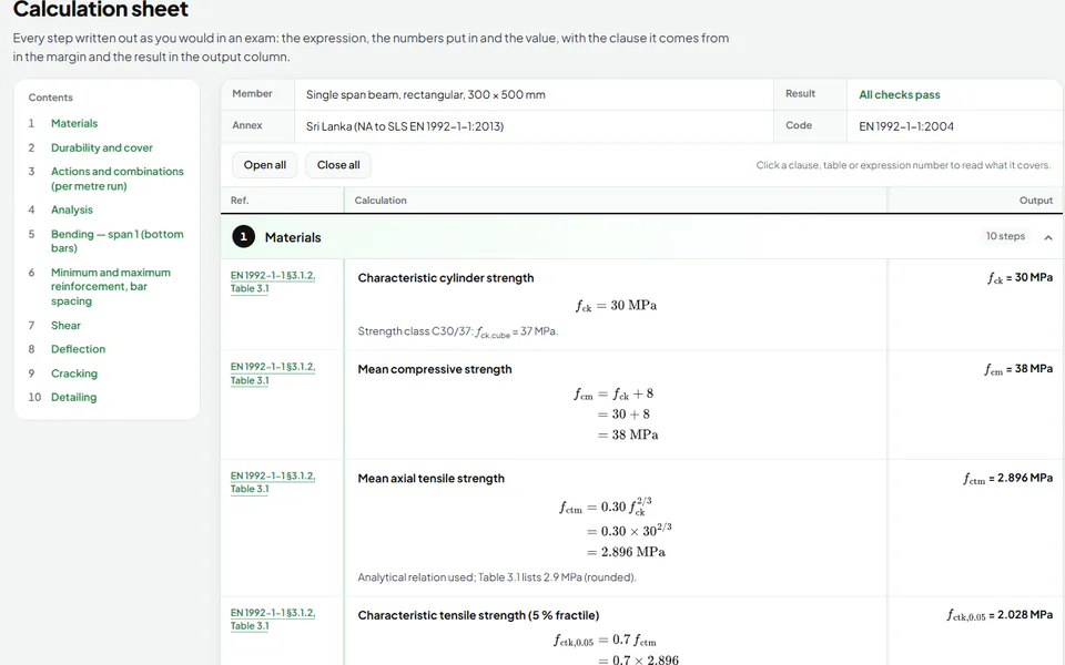
The beam calculator designs a reinforced concrete beam to EN 1992-1-1: the bottom and top bars at every span and support, the links, and the checks for deflection and cracking. It takes characteristic loads per metre run, analyses the beam itself, and sets out the whole calculation with its clauses.
This guide explains each group of inputs and what the results mean. The beam design worked example follows the calculator's example beam through the bending design line by line.
Beam type and spans
- Single span, pinned or fixed at each end.
- Continuous, over two to six spans. The calculator analyses it by the stiffness method under every load arrangement the National Annex asks for, and designs for the envelope.
- Cantilever, fixed at one end.
Enter the clear span of each span (between the faces of the supports) and the width of each support; the effective span adds half the support width, or half the depth if that is smaller, at each end (5.3.2.2).
The section
Three shapes are available:
| Shape | Inputs | How the flange is used |
|---|---|---|
| Rectangular | web width , depth | |
| T-beam | plus flange thickness and outstand each side | in compression at mid-span, with the effective width of 5.3.2.1 |
| L-beam | the same, with the flange on one side | as for a T-beam |
Over a support the flange is in tension, so the calculator designs the support section on the web alone. Beams deeper than a third of their span are deep beams, which need a different method; the calculator refuses them and says why.
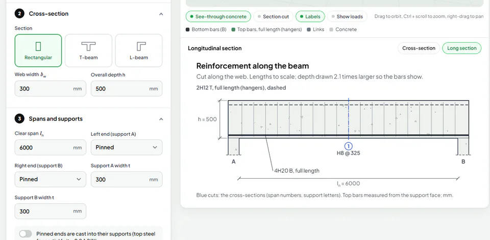
The section and span inputs, with the drawing switched to the long section.
- Rectangular, T or L section; T and L take the flange too
- Web width and overall depth
- Clear span between the faces of the supports
- The long section: bars, links and where they stop
Loads
The loads are characteristic values per metre run of beam:
- the superimposed dead load , to which the beam's own weight is added;
- the use category and imposed load ;
- an optional wind load, downward or uplift.
The calculator forms the ultimate combination by Expression 6.10 (or 6.10a and 6.10b), and the characteristic, frequent and quasi-permanent combinations for the serviceability checks. For the example beam (300 × 500 mm, 6000 mm clear span):
Characteristic permanent load
gsup is the superimposed permanent load per metre run: the slab, finishes and walls carried by the beam.
Characteristic imposed load
EN 1990 §A1.3.1(4), Table A1.2(B)
6.10
Bars and links
With Choose bars for me, the calculator picks the lightest bars that pass bending, the minimum steel and the bar spacing rules, and the lightest links that pass shear. The deflection and cracking checks then run on those bars. With Enter my own bars you choose:
- the number and diameter of the bottom bars, and of the top bars;
- the link diameter, number of legs and spacing.
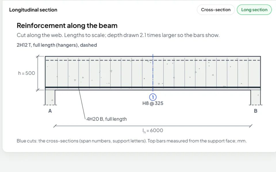
Bars are written as number, H and diameter, then B or T for the face: 1256.6 mm² of steel in the example comes from 4H20 B. Links are written as diameter, spacing and legs, such as H8 @ 325, 2 legs.
What the calculator checks
For each span and support, in this order:
- Loads, spans, and the envelope of every load arrangement
- Bending by the stress block (3.1.7), with a check that the tension steel yields
- Is x/d within the ductility limit of 5.5(4)?
Yes
- Tension steel only
No
- Compression steel as well
- Minimum and maximum steel (9.2.1.1), clear distance between bars (8.2)
- Shear: VRd,c, then links by the variable strut inclination method (6.2.3)
- Deflection by the span/effective depth ratio (7.4.2)
- Cracking under the quasi-permanent load (Tables 7.2N and 7.3N)
- Detailing: anchorage at the supports, laps, full-length top bars
The shear and links guide works through the shear step, with the minimum links and their spacing of 9.2.2.
Reading the result
The result header gives the bar schedule for every section, the links and the full-length top bars:
Required tension reinforcement
EN 1992-1-1 §8.2(2)
Bottom bars provided
4H20: one layer, 53 mm clear between bars. Fewest bars within 5 % of the lightest arrangement that fits. Considered: 4H20 (1257), 3H25 (1473), 2H32 (1608).
The checks table lists every check with its utilisation; the highest is the one to watch. Beside it are the bending moment and shear force diagrams, with every load arrangement in grey and the envelopes on top.
Under the 3D model, the drawing shows the cross-section of each span, or, switched to Long section, the reinforcement along the beam: each bar and where it stops, the links and their spacing, and blue cuts marking where the cross-sections are taken.
Tips
- A beam that fails deflection usually needs more depth, not more steel.
- If the links come out very close, check against : a web that is too thin cannot be fixed with links.
- For a continuous T-beam, look at the support sections: they are designed as rectangular, because the flange is in tension there.
Open the beam calculator and change any input to see every step worked out again.
Read next
-
 Design guide
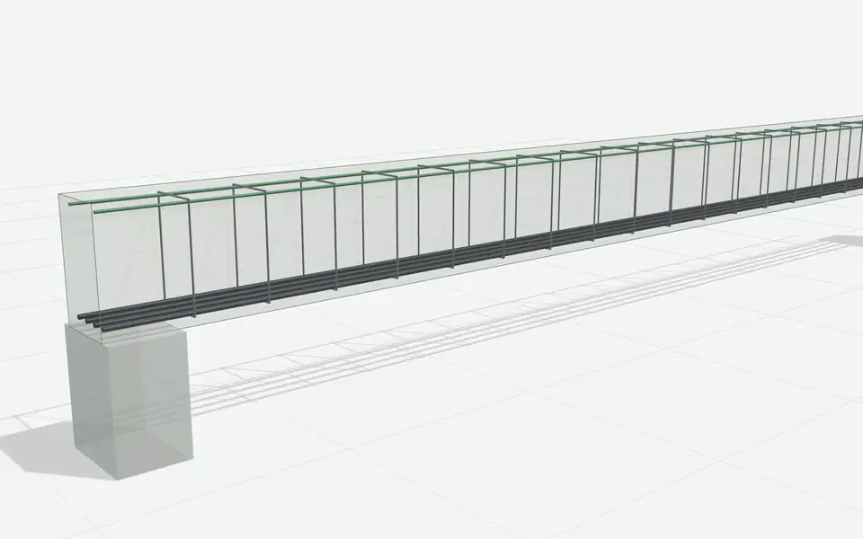
Beam design to Eurocode 2: a worked example of bending
A simply supported RC beam designed for bending to EN 1992-1-1, step by step: loads, design moment, effective depth, lever arm, steel area and bars.
-
 Design guide
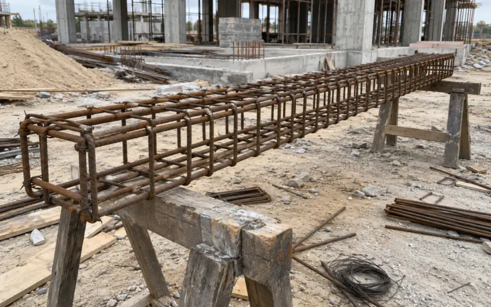
Shear design and links to Eurocode 2: a worked example
Shear and links to EN 1992-1-1, worked step by step: resistance without links, the variable strut inclination method, the crushing limit and minimum links.
-
 Calculator guide
How to use the Eurocode 2 calculator: a getting-started guide
A tour of the free Eurocode 2 calculator: choosing the member and National Annex, entering loads, reading the checks, and downloading the PDF.