
Design guide
Shear design and links to Eurocode 2: a worked example
Shear and links to EN 1992-1-1, worked step by step: resistance without links, the variable strut inclination method, the crushing limit and minimum links.
- Reading time
- 4 minutes
- Standard
- EN 1992-1-1
- Clauses
- 6.2.1, 6.2.2, 6.2.3, 9.2.2
- Calculator
- Beam
- Updated
On this page 6 sections
Shear in a reinforced concrete beam is checked in two stages in EN 1992-1-1. First, can the concrete carry the shear on its own? If not, links are designed by the variable strut inclination method, a truss in which the concrete forms inclined struts and the links form the ties.
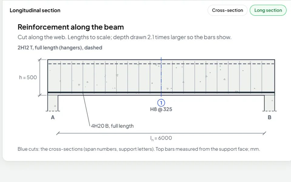
This guide continues the beam bending example: a 300 × 500 mm beam spanning 6000 mm, with a design load of 43.313 kN/m.
The answer, worked out below
- Design shear at d
- 110.01 kN
- VEd, at d from the face of the support
- Without links
- 82.76 kN
- VRd,c, less than VEd: links are needed
- Strut limit
- 384.42 kN
- VRd,max with cot θ = 2.5
- Links provided
- H8 @ 325, 2 legs
- VRd,s = 139.20 kN
The whole check is one decision followed by the truss:
- Design shear VEd at the face, and at d from it
- Resistance without links VRd,c (Expressions 6.2.a and 6.2.b)
- Is VEd ≤ VRd,c?
Yes
- Minimum links only (9.2.2)
No
- Design the links as the ties of a truss
- Flattest strut the web can carry, cot θ from 2.5 down to 1
- Asw/s = VEd / (z fywd cot θ)
- Provide at least the minimum links, ρw,min of 9.2.2(5)
- Spacing along the beam within sl,max = 0.75d
- Web crushing at the face of the support (6.5)
Step 1: The design shear
The shear is largest at the supports. The calculator takes it at the face of the support, and, for a beam carrying mainly a uniform load, again at a distance from the face, where clause 6.2.1(8) lets the check for the links be made:
Design shear at the right face of support A
At the face of the support: used for the strut checks (6.9 and 6.5).
Design shear at d from the face
For a uniformly loaded beam the links may be designed for the shear at d from the face (6.2.1(8)); this value is used for VRd,c and the links.
Step 2: Resistance without links
The shear resistance of a member without shear reinforcement is given by Expression 6.2.a, with a lower limit 6.2.b:
where is the size effect (deeper members are relatively weaker in shear), is the ratio of tension steel anchored beyond the section, and in the recommended values.
Size factor
d in mm.
Tension reinforcement ratio
Asl is the tension steel extending at least (lbd + d) beyond the section (Figure 6.3).
Minimum shear strength
EN 1992-1-1 §6.2.2(1), Eq. (6.2.b)
Shear resistance without shear reinforcement
Expression 6.2.a governs. σcp = 0 (no axial force).
EN 1992-1-1 §6.2.1(5)
Are designed links needed?
VEd (at d from the face of the support) exceeds VRd,c: links are designed for it (6.2.3).
Here is larger than , so designed links are needed. In a beam, clause 9.2.2 asks for at least minimum links anyway; slabs, by contrast, normally carry their shear without links.
Step 3: The strut angle and the crushing limit
In the truss model, the angle of the concrete struts may be chosen between (45°) and (about 21.8°) in the recommended values. A flatter strut means each link crosses a longer length of the crack, so fewer links are needed, but the struts are more highly stressed. The calculator tries the flattest strut first and checks that the web can carry it:
Strength reduction factor for concrete cracked in shear
ν₁ = ν and αcw = 1 (no prestress, no axial force).
Lever arm for shear
EN 1992-1-1 §6.2.3(2), Eq. (6.7N)
Strut resistance with cot θ = 2.5
VEd at the face is within VRd,max, so the flattest strut, cot θ = 2.5, is used (fewest links).
is well above , so can be used. If it were not, a steeper strut would be tried.
Step 4: The links
The links needed follow from the truss (Expression 6.8):
and they may not be less than the minimum of 9.2.2(5), , nor further apart than along the beam:
Links required for VEd
From (6.8) with VRd,s = VEd; VEd is taken at d from the face of the support (6.2.1(8), uniform load).
EN 1992-1-1 §9.2.2(5), Eq. (9.4)
Minimum links
Vertical links: α = 90°, sin α = 1.
Maximum spacing of links along the beam
Spacing of the link legs across the beam
2 legs, 248 mm apart. Sri Lanka NA: no tension bar more than 150 mm from a leg — the farthest bar is 87 mm from one.
EN 1992-1-1 §9.2.2(6)
Links provided
Spacing: sreq rounded down to 25 mm, not more than sl,max = 345.0 mm.
Here the minimum governs, which is common for lightly loaded beams. The links provided give a resistance of:
Shear resistance of the links
The resistance of the links falls in proportion as they spread out. The chart runs the calculator's own link check for this beam at every spacing up to : any spacing whose curve stays above carries the shear, and the lower dashed line shows what the concrete alone could carry.
Shear resistance of the links against their spacing
VRd,s from Expression 6.8 for the worked example's beam (z = 0.9d, cot θ = 2.5). Any spacing whose curve stays above VEd works; the spacing is also capped at sl,max = 345 mm.
- H8, 2 legs
- H10, 2 legs
Show the numbers
| Link spacing s (mm) | H8, 2 legs (kN) | H10, 2 legs (kN) |
|---|---|---|
| 150 | 301.6 | 471.2 |
| 175 | 258.5 | 403.9 |
| 200 | 226.2 | 353.4 |
| 225 | 201.1 | 314.2 |
| 250 | 181.0 | 282.7 |
| 275 | 164.5 | 257.0 |
| 300 | 150.8 | 235.6 |
| 325 | 139.2 | 217.5 |
How this differs from BS 8110
BS 8110 also starts from a concrete shear stress , but it fixes the strut at 45° and adds the concrete's share to the links. Eurocode 2 does not add the two: once links are needed, they carry the whole shear, but the flatter strut allowed by the variable angle makes them more efficient. The BS 8110 to Eurocode 2 guide lists the other differences.
Points to remember
Open the beam calculator and raise the load to see the links change, and the point at which the strut angle has to steepen.
Read next
-
 Design guide
Beam design to Eurocode 2: a worked example of bending
A simply supported RC beam designed for bending to EN 1992-1-1, step by step: loads, design moment, effective depth, lever arm, steel area and bars.
-
 Calculator guide
Beam design calculator to Eurocode 2: rectangular, T and L beams
Design a reinforced concrete beam to EN 1992-1-1 with the free calculator: spans and sections, loads, bending, links, deflection and cracking.
-
 Reference
From BS 8110 to Eurocode 2: what changes for reinforced concrete design
Moving from BS 8110 to EN 1992-1-1: concrete strength, partial factors, loads, bending, shear, deflection, cover and columns compared side by side.