
Design guide
Pad footing design to Eurocode 2: bearing, bending, punching shear and anchorage
A pad footing to EN 1992-1-1, worked step by step: ground pressure with eccentricity, bending at the face, beam shear, punching shear and anchorage.
- Reading time
- 5 minutes
- Standard
- EN 1992-1-1
- Clauses
- 6.2.2, 6.4.4, 6.4.5, 9.8.2
- Calculator
- Footing
- Updated
On this page 8 sections
A pad footing spreads a column load over enough ground to keep the bearing pressure within what the soil can take, and must be strong enough itself to carry that pressure back to the column. EN 1992-1-1 covers the concrete design: bending at the face of the column, beam shear, punching shear (6.4) and the anchorage of the bars (9.8.2).
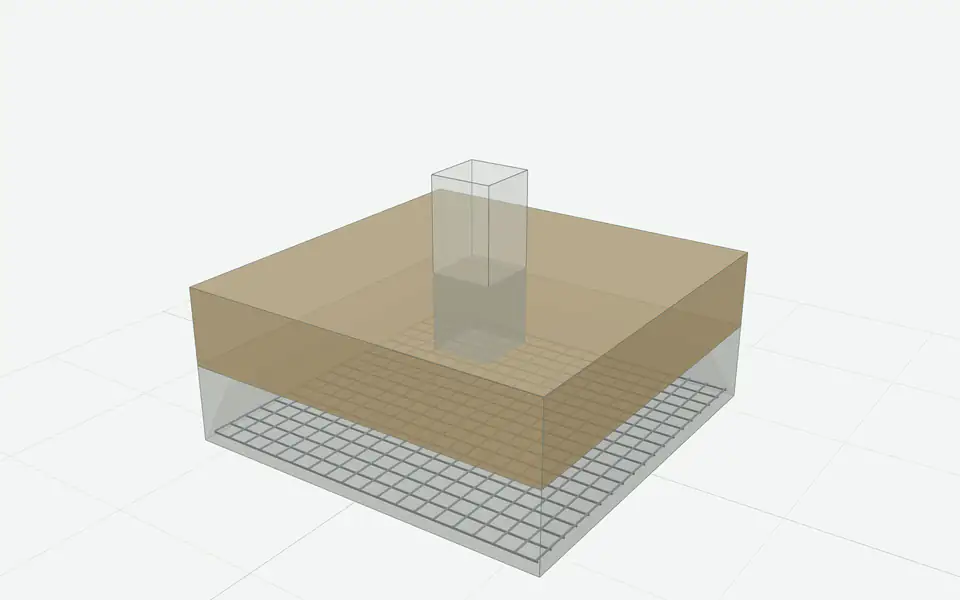
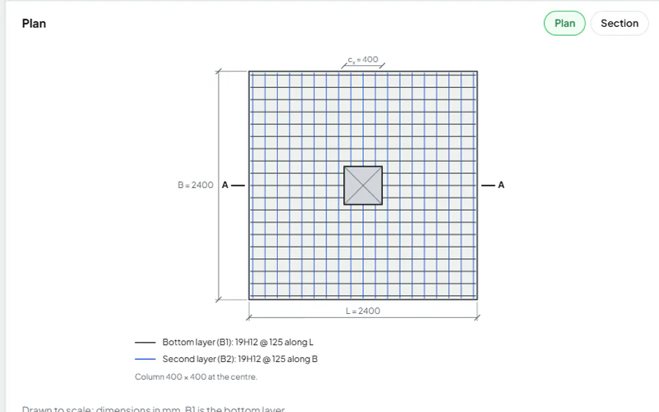
This guide works through the calculator's example: a 2400 × 2400 × 500 mm pad under a 400 × 400 mm column carrying = 900 kN and = 400 kN, with 500 mm of soil over it and a design bearing resistance of 400 kPa.
The answer, worked out below
- Ground pressure
- 343.8 kPa
- against σRd = 400 kPa
- Moment at the column face
- 378.13 kNm
- bars along L
- Bars, each way
- 19H12 @ 125
- As,prov = 2149 mm²
- Punching
- 0.750 MPa
- vEd at the governing perimeter
A footing is sized in two passes: its plan from the ground, its depth from the concrete.
- Column load Gk and Qk, a trial base L × B × h
- Total load on the ground: column, base and soil over it
- Is σmax ≤ σRd, with the load in the middle third?
Yes
- The plan size works
No
- Make the base larger in plan
- Net pressure from the column load alone
- Bending at each face of the column, bars both ways
- Beam shear at d from the face
- Punching at the column face, and on perimeters within 2d
- Does every check pass?
Yes
- The depth works
No
- Make the base deeper
- Anchor the bars beyond the critical section (9.8.2)
Step 1: Loads on the ground
The ultimate load from the column comes from Expression 6.10. The weights of the base and of the soil over it are added for the bearing check, since the ground carries those too:
Self-weight of the base
Reinforced normal-weight concrete, 25 kN/m³ (Table A.1).
Weight of the soil over the base
The backfill over the base, from your soil depth hs and unit weight γs.
EN 1990 §A1.3.1(4), Table A1.2(B)
Design load from the column (Expression 6.10)
This load alone causes the bending and shear in the base.
Total design load on the ground
Step 2: Ground pressure
For a concentric load the pressure is uniform, . With a moment it varies linearly; with the eccentricity ,
which is valid only while the whole base stays in compression, (the load in the middle third). The calculator refuses a base where part would lift off.
Ground pressure under the base
σRd is your design bearing resistance from EN 1997, which this tool does not derive. The ULS loads of EN 1990 Table A1.2(B) are used, so check that they match your EN 1997 design approach.
The design bearing resistance is your input from a geotechnical design to EN 1997; the tool does not derive it. For an eccentric load, here the calculator's second example with a moment about one axis:
Eccentricity of the load on the ground
With r ≤ 1 the load lies in the middle third (the kern) and the whole base presses on the ground.
Ground pressure under the base
σRd is your design bearing resistance from EN 1997, which this tool does not derive. The ULS loads of EN 1990 Table A1.2(B) are used, so check that they match your EN 1997 design approach.
Step 3: Bending at the face of the column
The base bends upward like an inverted cantilever beyond each face of the column.
Cantilever beyond the column face, along L
Bending moment at the column face (bars along L)
From the net upward pressure of the column load only: the weights of the base and the soil over it rest on their own share of the ground pressure. Pressures in kPa.
The steel is then designed as for a beam, over the full width of the base, with the second layer of bars at a slightly smaller effective depth:
Effective depth, bars along L
The bottom layer.
Required tension reinforcement
EN 1992-1-1 §9.3.1.1(1)
Minimum tension reinforcement
b = 2400 mm, the full width the bars are spread over.
EN 1992-1-1 §8.2(2)
Bars along L
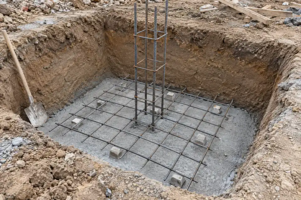
19H12 @ 125 mm across 2400 mm: the lightest that passes; smax = 250 mm.
Step 4: Beam shear
Beam shear is checked on a section at from the face of the column across the full width, against (Expression 6.2.a). The shear is the net pressure on the area beyond that section:
EN 1992-1-1 §6.2.2(1)
Shear at d from the column face, along L
The net upward pressure (column load only) beyond d from the face, over the full width. Pressures in kPa.
EN 1992-1-1 §6.2.2(1), Eq. (6.2.b)
Shear resistance without shear reinforcement
vmin governs (Expression 6.2.b). σcp = 0 (no axial force); N in N, lengths in mm.
Shear check
No shear reinforcement is needed.
Step 5: Punching shear
Punching is the column pushing a cone of concrete out of the base. EN 1992-1-1 checks it in two places:
At the column face, the shear stress on the perimeter of the column must not exceed the crushing limit (6.4.5(3)):
EN 1992-1-1 §6.4.4(1)
Mean effective depth and steel ratio for punching
The bars are spread evenly over the base, so each ratio over the full width equals the ratio over the column width plus 3d each side (6.47).
Perimeter of the column
Punching stress at the column face
The full column load at the face, without the soil-pressure deduction (conservative). d is the mean of the two layers.
On control perimeters at a distance from the face, with rounded corners. For a slab the basic control perimeter is at ; in a footing, the ground pressure inside the perimeter relieves the shear, so clause 6.4.4(2) asks for perimeters within to be checked, with:
The resistance rises as the perimeter comes closer to the column ( grows), but so does the stress; the calculator tries perimeters from to and reports the one that governs:
Punching resistance at 2d (no shear reinforcement)
ρl = √(ρlx ρly) from the bars of both layers, at most 0.02.
EN 1992-1-1 §6.4.4(2), Eq. (6.50)
EN 1992-1-1 §6.4.4(2), Eq. (6.49)
Punching at the governing perimeter (a = 407 mm)
Perimeters from 0.1d to 2d were checked; this one has the least margin. The soil pressure inside it (σnet in kPa) is deducted (6.4.3(8), 6.48).
Drawn out over the perimeters, the two effects pull against each other. Here is the calculator's own punching check run at each distance for this base:
Punching across the perimeters within 2d
The pad of the worked example: NEd = 1815 kN on a 400 × 400 column, d = 448 mm. Close to the column the stress is high but so is the resistance, which grows as 2d/a; farther out, the ground pressure inside the perimeter takes load off VEd. The worst ratio lies in between.
- vEd, design stress
- vRd,c·2d/a, resistance
Show the numbers
| Distance of the perimeter from the column face a (mm) | vEd, design stress (MPa) | vRd,c·2d/a, resistance (MPa) |
|---|---|---|
| 224 | 1.189 | 1.652 |
| 269 | 1.057 | 1.376 |
| 314 | 0.943 | 1.179 |
| 358 | 0.845 | 1.034 |
| 403 | 0.757 | 0.918 |
| 448 | 0.678 | 0.826 |
| 493 | 0.606 | 0.751 |
| 538 | 0.541 | 0.688 |
| 582 | 0.482 | 0.636 |
| 627 | 0.427 | 0.590 |
| 672 | 0.375 | 0.551 |
| 717 | 0.327 | 0.516 |
| 762 | 0.282 | 0.486 |
| 806 | 0.240 | 0.459 |
| 851 | 0.199 | 0.435 |
| 896 | 0.160 | 0.413 |
If punching fails, the answer is a deeper base: shear reinforcement in footings is possible but rarely economic, and the calculator does not design it.
Step 6: Anchorage of the bars
The bars must be anchored beyond the critical section of Figure 9.13. The calculator takes the simplified section at from the edge and works out the force there from the pressure on the part of the base outside it:
with and from the pressure resultant to a line times the column width inside its face. Straight bars must then have a length at least equal to for the stress :
EN 1992-1-1 §9.8.2.2(1), Figure 9.13
Section for the anchorage of the bars along L
For straight bars without end anchorage the section nearest the edge is the most critical; x = h/2 is the simplification allowed.
Ground pressure within x of the edge
The net upward pressure (column load only) over the strip of base between the edge and x. Pressures in kPa, lengths in m.
EN 1992-1-1 §9.8.2.2(3)
Tensile force to anchor at x
ze runs from R (at x/2 from the edge), to the column load taken 0.15c inside the face; zi = 0.9d is the simplification allowed.
EN 1992-1-1 §9.8.2.2(1), Figure 9.13
Straight length available beyond x
Straight bars are anchored within x of the edge.
This is why the calculator often chooses small bars at a close spacing in a footing: the anchorage length grows with the bar diameter, while the room beyond is fixed by the depth.
The answer
The 500 mm base passes every check with two layers of 19H12 @ 125: 2149 mm² each way, against 1960.73 mm² needed along L. The ground pressure is 343.8 kPa against the 400 kPa allowed, and the anchorage of the bars is the check closest to its limit.
Points to remember
- Use the net pressure (column load only) for bending and shear, and the total (with base and soil) for bearing.
- Keep the load in the middle third; otherwise make the base larger.
- Cover on blinding is at least 40 mm, and 75 mm when cast directly against the ground (4.4.1.3(4)).
- Check punching on perimeters within , not only at , because the ground pressure inside the perimeter reduces the shear.
Open the footing calculator and try a thinner base to see punching govern.
Read next
-
 Calculator guide
Footing design calculator to Eurocode 2: pad and strip footings
Design a pad or strip footing to EN 1992-1-1 with the free calculator: bearing pressure, bending at the face, beam shear, punching and anchorage.
-
 Design guide
Shear design and links to Eurocode 2: a worked example
Shear and links to EN 1992-1-1, worked step by step: resistance without links, the variable strut inclination method, the crushing limit and minimum links.
-
 Design guide
Load combinations and concrete cover to the Eurocodes: 6.10, 6.10a, 6.10b and nominal cover
How EN 1990 combines loads (Expressions 6.10, 6.10a, 6.10b and the SLS combinations) and how EN 1992-1-1 sets the nominal cover to the steel.