
Design guide
Beam design to Eurocode 2: a worked example of bending
A simply supported RC beam designed for bending to EN 1992-1-1, step by step: loads, design moment, effective depth, lever arm, steel area and bars.
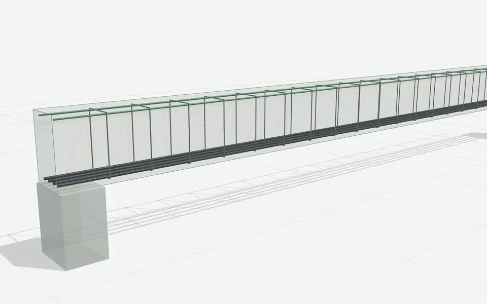
- Reading time
- 5 minutes
- Standard
- EN 1992-1-1
- Clauses
- 3.1.6, 3.1.7, 4.4.1, 5.5, 6.1, 9.2.1.1
- Calculator
- Beam
- Updated
On this page 9 sections
This worked example designs a simply supported reinforced concrete beam for bending to EN 1992-1-1, the way an exam answer sets it out. Every number in the steps below comes from the free beam calculator, which writes each step with the clause it uses.
The answer, worked out below
- Design moment
- 214.88 kNm
- at mid-span, Expression 6.10
- Effective depth
- 460 mm
- to the centre of the H20 bars
- Lever arm
- 408.4 mm
- from the rectangular stress block
- Steel needed
- 1210.12 mm²
- As,req = MEd / (fyd z)
- Bars provided
- 4H20
- As,prov = 1256.6 mm²
The brief
A rectangular beam, 300 mm wide and 500 mm deep, spans 6000 mm between the faces of two 300 mm wide supports. It carries a superimposed dead load of 15 kN/m and an imposed load of 12 kN/m (offices, category B), in C30/37 concrete with 500 MPa steel, exposure class XC1, under the Sri Lanka National Annex.
Design the bottom steel at mid-span.
Every bending design follows the same path, whatever the member. The steps below take it one box at a time:
- Loads, span, section and materials
- Design load wd from Expression 6.10 of EN 1990
- Design moment MEd at mid-span
- Nominal cover cnom, then the effective depth d
- Depth of the stress block from MEd = η fcd b a (d − a/2)
- Is x/d within the ductility limit of 5.5(4)?
Yes
- Lever arm z = d − a/2
No
- Deepen the section, or add compression steel
- Steel area As,req = MEd / (fyd z)
- Bars with As,prov ≥ As,req, then As,min and As,max
- On to shear, deflection and cracking
Step 1: Material strengths
The design strength of the concrete is the characteristic cylinder strength divided by the partial factor, times for long-term effects, which the National Annex sets:
EN 1992-1-1 §2.4.2.4(1), Table 2.1N
Design compressive strength
EN 1992-1-1 §2.4.2.4(1), Table 2.1N
Design yield strength (horizontal top branch)
Assumption (b) of 3.2.7(2): no strain limit needs checking. Es = 200 GPa (3.2.7(4)).
The Sri Lanka annex uses ; the CEN recommended value is 1.0. That one choice changes the steel area by a few per cent, which is why the calculator always names the annex it used.
Step 2: Cover and effective depth
The cover protects the steel and lets it bond to the concrete. For exposure class XC1 the durability cover comes from Table 4.4N, the bond cover is at least the bar diameter, and the allowance for deviation is added (4.4.1). The links need cover, and so do the main bars inside them: here the 20 mm main bars need more for bond than the links do, so their cover governs and the links sit just inside it:
Nominal cover (links H8)
EN 1992-1-1 §4.4.1.3(1)P
Cover to the main bars (H20)
The links alone need cnom = 20 mm, but the main bars need more: cnom is raised to 22 mm so that cnom + φw = cmin,b + Δcdev.
Step 3: Design load and moment
The self-weight is 25 kN/m³ × 0.3 m × 0.5 m. The ultimate design load comes from Expression 6.10 of EN 1990, with and :
Self-weight of the beam
Reinforced normal-weight concrete: 24 kN/m³ + 1 kN/m³ for reinforcement (Table A.1, footnote 1).
Characteristic permanent load
gsup is the superimposed permanent load per metre run: the slab, finishes and walls carried by the beam.
EN 1990 §A1.3.1(4), Table A1.2(B)
6.10
The effective span adds half a support width at each end, and for a simply supported beam the design moment is :
EN 1992-1-1 §5.3.2.2(1), Figure 5.4
Effective span 1
Design bending moment
Step 4: The stress block and the lever arm
Eurocode 2 lets the concrete in compression be replaced by a rectangular block of depth at a stress (3.1.7(3)), with and for concrete up to C50/60. Taking moments about the steel gives the depth of the block directly:
Effective depth
H20 bars inside H8 links, with the nominal cover cnom to the links.
EN 1992-1-1 §6.1(2)P
Depth of the rectangular stress block, from moment equilibrium
Taking moments about the tension steel and solving the quadratic for a.
Neutral axis depth
The neutral axis must not be too deep, so that the section is ductile: the steel yields well before the concrete crushes. Clause 5.5(4) relates the limit on to the redistribution, with constants from the National Annex:
Ductility limit on x/d
δ = 1 (no redistribution).
EN 1992-1-1 §6.1(2)P
Strain in the tension steel
The steel yields, so the design stress fyd can be used (Es = 200 GPa, from the strain diagram).
The lever arm is then the distance from the steel to the middle of the block:
EN 1992-1-1 §6.1(2)P
Lever arm
The same result by the K method
Many textbooks and the UK How to guides write this as a formula in . With and the equilibrium above becomes
and singly reinforced design is allowed while , where follows from the limit on (0.167 for , a common UK choice). It is the same mechanics in a different form; the calculator solves the equilibrium directly so that any from any annex flows through.
The steel a section needs rises faster than the moment, because the lever arm shortens as the block deepens. Here is the calculator's own bending check run over a range of moments for this beam, up to where it would stop being singly reinforced:
Steel needed as the moment grows
The 300 × 500 beam of the worked example, d = 460 mm, C30/37. The curve steepens as the lever arm z shortens, and stops where x/d reaches its limit: beyond it the section needs compression steel.
Show the numbers
| Design moment MEd (kNm) | As,req (mm²) |
|---|---|
| 20.0 | 101 |
| 60.0 | 309 |
| 100.0 | 526 |
| 140.0 | 752 |
| 180.0 | 991 |
| 220.0 | 1243 |
| 260.0 | 1512 |
| 300.0 | 1800 |
| 340.0 | 2114 |
| 380.0 | 2461 |
| 393.7 | 2590 |
Step 5: Steel area and bars
With the lever arm known, the steel force must balance the moment, and the steel works at its design yield strength :
Required tension reinforcement
EN 1992-1-1 §8.2(2)
Bottom bars provided
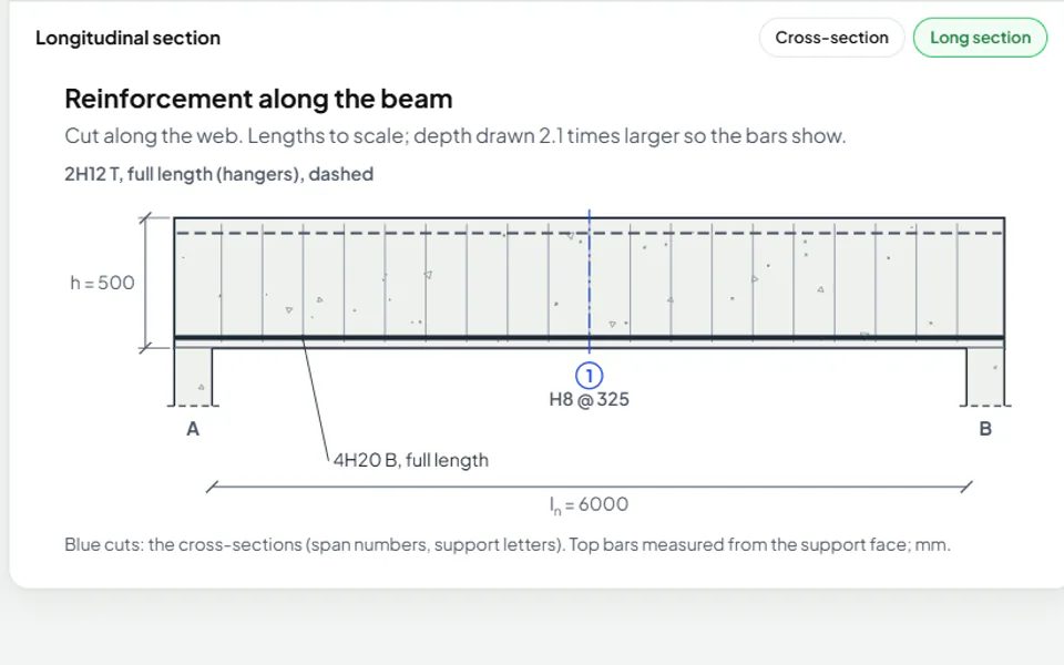
4H20: one layer, 53 mm clear between bars. Fewest bars within 5 % of the lightest arrangement that fits. Considered: 4H20 (1257), 3H25 (1473), 2H32 (1608).
Step 6: Minimum and maximum steel, bar spacing
A beam must have enough steel not to fail suddenly when the concrete cracks (9.2.1.1(1)), not so much that it cannot be compacted (9.2.1.1(3)), and room between the bars for the concrete to flow (8.2):
Minimum tension reinforcement (bottom bars)
bt = bw = 300 mm.
Maximum reinforcement outside laps
Ac is taken as the web bw h (conservative for a flanged beam); the largest face is the bottom bars.
Minimum clear distance between bars (bottom bars)
sclear = (bw − 2(cnom + φw) − n φ)/(n − 1) for the 4 bars of the outer layer.
The answer
Provide 4H20 bottom bars (1256.6 mm²) at mid-span, against 1210.12 mm² required. The full design goes on to the links, deflection and cracking:
- the shear and links guide designs the links for this beam;
- the deflection and cracking guide explains the serviceability checks.
Common mistakes in exams
- Using the cube strength. EN 1992-1-1 works with the cylinder strength : C30/37 means = 30 MPa.
- Forgetting the self-weight. It is often 10 to 20 % of the load on a beam.
- Taking to the bottom of the bars. The effective depth runs to the centre of the tension steel.
- Skipping the ductility limit. If is too large, add compression steel or deepen the section; more tension steel alone does not help.
Open the beam calculator to change the span, the loads or the section and see every step worked out again.
Read next
-
 Design guide
Shear design and links to Eurocode 2: a worked example
Shear and links to EN 1992-1-1, worked step by step: resistance without links, the variable strut inclination method, the crushing limit and minimum links.
-
 Calculator guide
Beam design calculator to Eurocode 2: rectangular, T and L beams
Design a reinforced concrete beam to EN 1992-1-1 with the free calculator: spans and sections, loads, bending, links, deflection and cracking.
-
 Design guide
Load combinations and concrete cover to the Eurocodes: 6.10, 6.10a, 6.10b and nominal cover
How EN 1990 combines loads (Expressions 6.10, 6.10a, 6.10b and the SLS combinations) and how EN 1992-1-1 sets the nominal cover to the steel.