
Calculator guide
Footing design calculator to Eurocode 2: pad and strip footings
Design a pad or strip footing to EN 1992-1-1 with the free calculator: bearing pressure, bending at the face, beam shear, punching and anchorage.
- Reading time
- 3 minutes
- Standard
- EN 1992-1-1
- Clauses
- 4.4.1.3, 6.2.2, 6.4, 9.8.2
- Calculator
- Footing
- Updated
On this page 6 sections
The footing calculator designs a reinforced concrete pad footing under a column, or a strip footing under a wall, to EN 1992-1-1. From the characteristic loads and your design bearing resistance it checks the ground pressure, designs the bottom bars both ways, and checks beam shear, punching shear and the anchorage of the bars.
Pad or strip
- Pad under a column: a rectangular base and depth , with a rectangular column at its centre. Bending is designed in both directions.
- Strip under a wall: a strip of width and depth under a wall of thickness , designed per metre run. Its main bars run across the strip, with distribution bars along the wall.
Each type keeps its own sizes and loads, so you can switch between them and back without losing either.
The ground
- Design bearing resistance , in kPa. This comes from your geotechnical design to EN 1997, which the calculator does not do.
- Soil over the base: the depth of backfill and its unit weight. Its weight is added to the load on the ground.
- Cast on blinding or against soil: this sets the minimum cover of 4.4.1.3(4), 40 mm on blinding or 75 mm against soil in the recommended values.
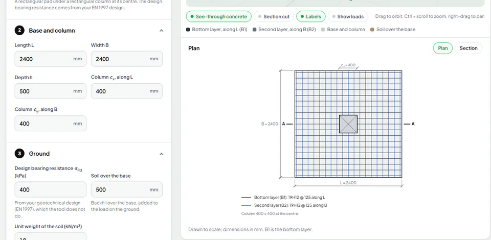
The base, column and ground inputs, with the plan of the example pad beside them.
- The base: length, width and depth
- The column or wall it carries
- The ground: design bearing resistance and the soil over the base
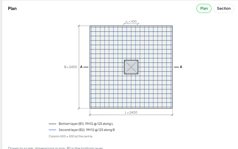
- Plan and section of the base, to scale
Loads
Enter the characteristic loads at the base of the column (kN) or wall (kN/m): , , the use category, and any moments from G and Q. For a pad, a moment makes the pressure vary along L and along B. The calculator adds the weights of the base and the soil and combines everything by Expression 6.10, or the less favourable of 6.10a and 6.10b.
What the calculator checks
The ground pressure uses the eccentricity ; the rest uses the net upward pressure of the column load only, since the base and the soil carry their own weight to the ground.
- Characteristic loads, the base size, and σRd of the ground
- Ground pressure, with the weight of the base and the soil over it
- Is the load in the middle third, with σmax ≤ σRd?
Yes
- On to the concrete
No
- The calculator asks for a larger base
- Bending at the face of the column or wall, bars both ways
- Beam shear at d from the face, against VRd,c
- Punching (pads): at the column face, and on perimeters out to 2d
- Anchorage beyond the critical section of Figure 9.13 (9.8.2.2)
- Minimum steel and the smallest bar allowed in a base
For the calculator's example pad, 2400 × 2400 × 500 mm under a 400 mm square column:
EN 1990 §A1.3.1(4), Table A1.2(B)
Design load from the column (Expression 6.10)
This load alone causes the bending and shear in the base.
Total design load on the ground
Ground pressure under the base
σRd is your design bearing resistance from EN 1997, which this tool does not derive. The ULS loads of EN 1990 Table A1.2(B) are used, so check that they match your EN 1997 design approach.
Reading the result
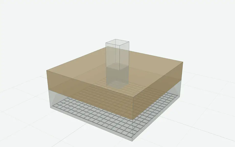
The result header gives the bars each way, such as 19H12 @ 125 along L and along B, with B1 for the bottom layer and B2 for the layer laid on it. The model beside the inputs shows the 3D base with the soil drawn see-through, and a plan and section drawn to scale.
The checks table shows the bearing pressure, bending each way, beam shear each way, punching at the face and at the governing perimeter, anchorage and minimum steel. In the example the anchorage of the bars is the check closest to its limit: straight bars need room beyond the critical section, which is why the calculator often picks smaller bars at a closer spacing.
Tips
- If punching or shear fails, deepen the base: the calculator does not design shear reinforcement in footings.
- If the anchorage fails, smaller bars at a closer spacing usually solve it, since the anchorage length grows with the bar size.
- If bearing fails, the base must be larger in plan; a deeper base only adds weight.
- The pad footing and punching shear guide works through the whole example step by step.
Open the footing calculator to try your own footing.
Read next
-
 Design guide
Pad footing design to Eurocode 2: bearing, bending, punching shear and anchorage
A pad footing to EN 1992-1-1, worked step by step: ground pressure with eccentricity, bending at the face, beam shear, punching shear and anchorage.
-
 Calculator guide
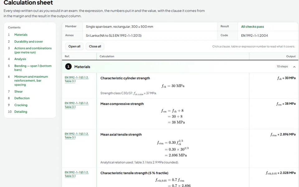
How to use the Eurocode 2 calculator: a getting-started guide
A tour of the free Eurocode 2 calculator: choosing the member and National Annex, entering loads, reading the checks, and downloading the PDF.
-
 Design guide
Load combinations and concrete cover to the Eurocodes: 6.10, 6.10a, 6.10b and nominal cover
How EN 1990 combines loads (Expressions 6.10, 6.10a, 6.10b and the SLS combinations) and how EN 1992-1-1 sets the nominal cover to the steel.