
Calculator guide
Column design calculator to Eurocode 2: braced, unbraced and slender columns
Design a rectangular RC column to EN 1992-1-1 with the free calculator: end restraints, loads, slenderness, second order moments and biaxial bending.
- Reading time
- 4 minutes
- Standard
- EN 1992-1-1
- Clauses
- 5.2, 5.8, 6.1, 9.5
- Calculator
- Column
- Updated
On this page 6 sections
The column calculator designs a rectangular reinforced concrete column between two floors to EN 1992-1-1. It finds the effective length and slenderness about both axes, adds the imperfections and, for a slender column, the second order moment by the nominal curvature method (5.8.8), then designs the bars for bending about each axis and checks the two together.
Axes and section
The calculator follows the axes of EN 1992-1-1 Figure 5.8: the depth h lies along y and the width b along z, so a moment about z bends the column across its depth h. Enter:
- b and h, and the clear height l between the floors;
- a section more than four times as long as it is wide is a wall, and the calculator refuses it.
End restraints
The effective length depends on how stiffly the floors hold the column ends, separately about each axis. Choose either:
- From and , the relative flexibilities at the top and bottom: 0 for a rigid restraint, larger for a flexible one, with 0.1 as the least used. Tick braced if the ends do not sway; the calculator uses Expression 5.15 for a braced column and 5.16 for an unbraced one.
- A Figure 5.7 case, one of the idealised columns of that figure, from fixed at both ends to a free-standing cantilever.
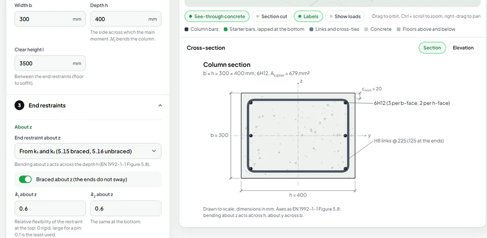
The height and end restraint inputs, with the example column's drawing beside them.
- Clear height between the restraints
- End restraints about each axis set the effective length
- Braced or unbraced: whether the ends can sway
- The section and elevation, to scale
Actions
There are two ways to give the loads:
- Characteristic loads (the default): and from the floors above, the use category, and the end moments from G and Q about each axis. The calculator adds the column's own weight if you tick it, combines the loads by Expression 6.10 (or 6.10a/6.10b), and works out the share of the moment that is quasi-permanent, which it needs for creep.
- Design values: and the first order end moments straight from your own frame analysis, plus the quasi-permanent share (about 0.6 to 0.7 in usual buildings).
What the calculator works out
About each axis in turn:
- Effective length l0 from the end restraints (5.15, 5.16 or Figure 5.7)
- Slenderness λ = l0 / i, and its limit λlim (5.13N)
- Imperfection: ei = θi l0 / 2 added to the end moments (5.2)
- Is λ ≤ λlim?
Yes
- First order moments only
No
- Second order moment M2 by nominal curvature (5.8.8)
- Design moment: the largest of M02, M0e + M2 and NEd e0
- Resistance from the N–M interaction curve, by strain compatibility
- Biaxial bending (5.39), then the detailing
The detailing covers the smallest bar, the minimum and maximum steel, the link size and spacing (closed up near the floors and over the lap), and the lap length.
The calculator's braced example column, 300 × 400 mm and 3500 mm high under 1600 kN, is short about z but slender about y, because its only moments about y come from the imperfection and are equal at both ends:
Slenderness about z
Slenderness limit about z
ω from the bars provided; rm = M₀₁/M₀₂ with the first order end moments (positive when both give tension on the same side).
Slenderness about y
Slenderness limit about y
ω from the bars provided; C = 0.7 because rm = 1 where the first order moments come mainly from the imperfection (NEd·ei is at least the larger applied end moment), 5.8.3.1(1).
Reading the result
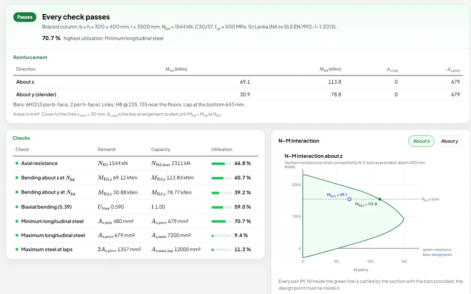
The result header gives the bars as a total with the count on each face, for example 6H12 (3 per b-face, 2 per h-face), the links with their closer spacing near the floors, and the lap. The table gives , and the steel about each axis.
The interaction diagram beside the checks shows every pair of N and M the section can carry; the design point must lie inside the green line:
Tips
- If a column is slender about one axis only, check the restraint inputs first: the effective length is often the easiest thing to improve.
- A higher axial load makes the slenderness limit smaller ( falls with ), so a column can become slender as the load rises.
- The column slenderness guide follows a slender column through the nominal curvature method, step by step.
Open the column calculator to try your own column.
Read next
-
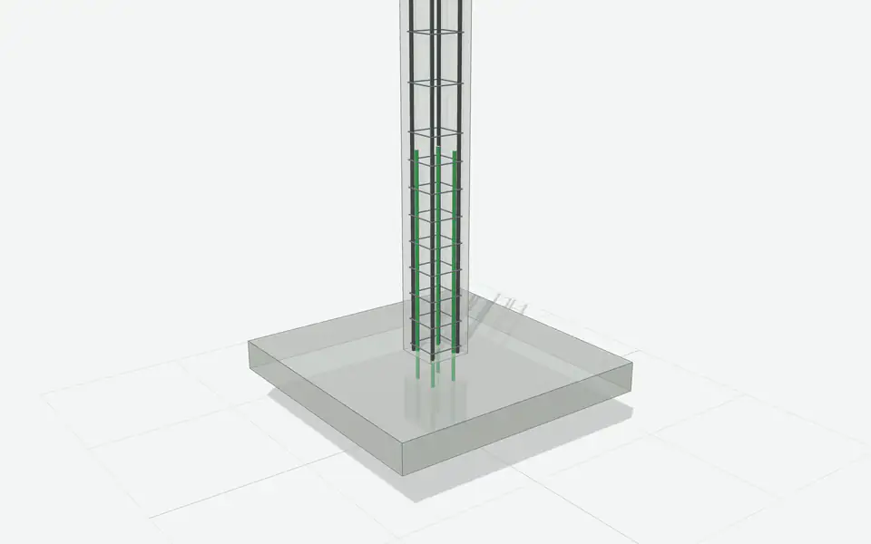 Design guide
Column slenderness to Eurocode 2: effective length, slenderness limit and nominal curvature
A slender braced column to EN 1992-1-1, worked step by step: effective length, slenderness and its limit, imperfections, and the nominal curvature method.
-
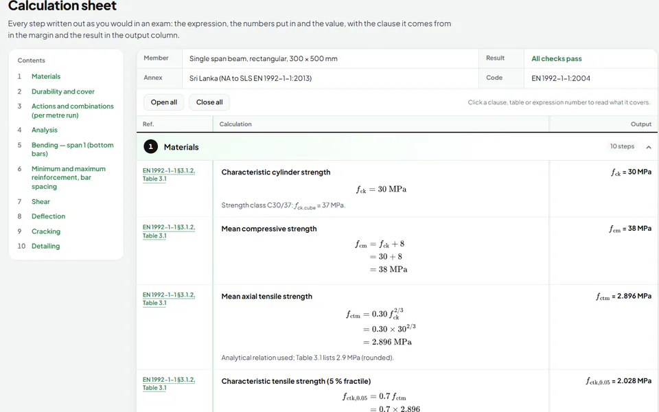 Calculator guide
How to use the Eurocode 2 calculator: a getting-started guide
A tour of the free Eurocode 2 calculator: choosing the member and National Annex, entering loads, reading the checks, and downloading the PDF.
-
 Design guide
Load combinations and concrete cover to the Eurocodes: 6.10, 6.10a, 6.10b and nominal cover
How EN 1990 combines loads (Expressions 6.10, 6.10a, 6.10b and the SLS combinations) and how EN 1992-1-1 sets the nominal cover to the steel.