
Design guide
Column slenderness to Eurocode 2: effective length, slenderness limit and nominal curvature
A slender braced column to EN 1992-1-1, worked step by step: effective length, slenderness and its limit, imperfections, and the nominal curvature method.
- Reading time
- 4 minutes
- Standard
- EN 1992-1-1
- Clauses
- 5.2, 5.8.3, 5.8.8
- Calculator
- Column
- Updated
On this page 8 sections
A column that is long for its size bends sideways under its own axial load, and that sideways deflection adds a moment: the second order effect. EN 1992-1-1 decides whether a column is slender by comparing its slenderness with a limit , and, if it is, adds the extra moment, most simply by the nominal curvature method of 5.8.8.
This guide works through the calculator's slender example: a 300 × 300 mm braced column, 6000 mm high between floors, carrying 900 kN with equal end moments of 40 kNm about z.
The answer, worked out below
- Slenderness
- 58.5
- λ about z, with l0 = 5069 mm
- Limit
- 19.7
- λlim from Expression 5.13N: the column is slender
- Second order moment
- 44.09 kNm
- M2 by nominal curvature
- Design moment
- 93.41 kNm
- MEd about z, against MRd = 128.54 kNm
The steps below follow this path, once for each axis:
- Effective length l0 from the end restraints (5.15)
- Slenderness λ = l0 / i
- Limit λlim = 20 A B C / √n (5.13N)
- Is λ ≤ λlim?
Yes
- Not slender: first order moments with the imperfection
No
- Slender: add the second order moment
- Curvature 1/r = Kr Kφ / r0, deflection e2 = (1/r) l0² / c
- MEd = max(M02; M0e + M2; NEd e0)
- Check NEd with MEd on the N–M interaction curve
- Biaxial bending, if both axes carry moment (5.39)
Step 1: Effective length
The effective length is the length of a pin-ended column with the same buckling load. For a braced column it follows from the restraint at each end (Expression 5.15):
where and are the relative flexibilities of the restraints at the two ends: 0 for full fixity (giving ) and infinity for a pin (giving ). This example takes , a fairly flexible restraint.
Effective length about z (braced)
k = (θ/M)(EI/l) is the relative flexibility of the end restraint (0 rigid, ∞ pinned); 0.1 is the smallest value used.
Step 2: Slenderness
The slenderness ratio is the effective length divided by the radius of gyration of the concrete section, for a rectangle bending across :
Radius of gyration about z
Uncracked concrete section; h is the depth in this direction.
Slenderness about z
Step 3: The slenderness limit
A column needs no second order moment if , where (Expression 5.13N)
- allows for creep, through the effective creep ratio ;
- allows for the steel, with ;
- allows for the shape of the moment diagram, with .
The moment ratio matters most. Equal moments in single curvature () give ; equal and opposite moments () give , almost four times the limit. This column has equal moments, the worst case:
Moment ratio about z
Effective creep ratio
M0Eqp/M0Ed is the ratio of the quasi-permanent to the design first order moment, entered with the actions.
Slenderness limit about z
ω from the bars provided; rm = M₀₁/M₀₂ with the first order end moments (positive when both give tension on the same side).
EN 1992-1-1 §5.8.2(6)
Second order effects about z
The column is slender in this direction: the second order moment is added (5.8.8).
The limit falls as the axial force rises, and the moment ratio moves it a long way. Here is Expression 5.13N worked by the calculator for this column's creep and steel, for the three classic moment shapes, with its own slenderness drawn across:
Slenderness limit against the axial force
λlim = 20·A·B·C/√n for a braced column with φef = 1.73 and ω = 0.558, as in the worked example. A column whose λ lies above its curve is slender and needs second order moments.
- rm = 1, equal end moments
- rm = 0, one end moment
- rm = −1, double curvature
Show the numbers
| Relative axial force n | rm = 1, equal end moments | rm = 0, one end moment | rm = −1, double curvature |
|---|---|---|---|
| 0.20 | 33.8 | 82.2 | 130.5 |
| 0.30 | 27.6 | 67.1 | 106.5 |
| 0.40 | 23.9 | 58.1 | 92.3 |
| 0.50 | 21.4 | 52.0 | 82.5 |
| 0.60 | 19.5 | 47.4 | 75.3 |
| 0.70 | 18.1 | 43.9 | 69.7 |
| 0.80 | 16.9 | 41.1 | 65.2 |
| 0.90 | 15.9 | 38.7 | 61.5 |
| 1.00 | 15.1 | 36.7 | 58.3 |
With equal end moments this column is slender over the whole range drawn; in double curvature the same column would not be slender until reached about 1.
Step 4: Imperfections
Every real column is a little out of line. Clause 5.2 allows for it with an inclination , reduced for taller members by , which for an isolated member becomes an eccentricity , added to the end moments:
Inclination of the imperfection
Eccentricity for imperfections about z
EN 1992-1-1 §5.2(7)
Larger first order end moment about z, with the imperfection
First order effects include the geometric imperfections (5.8.1), so NEd·ei is added to the end moments in the direction that increases the larger one.
Smaller first order end moment about z, with the imperfection
M₀₁ has the same sign as M₀₂ when both give tension on the same side (single curvature), and the opposite sign in double curvature.
Step 5: The second order moment by nominal curvature
The nominal curvature method estimates the deflection at mid-height from the curvature at which the steel yields, reduced or increased for the actual axial load and for creep:
- falls as the axial load rises, because a highly loaded section fails by crushing before the steel yields;
- increases the curvature for creep;
- (close to ) for a column of constant section.
Basic curvature about z
d in metres, so the curvature is per metre.
Correction factor for axial load
nbal = 0.4, the value of n at the largest moment resistance that 5.8.8.3(3) allows.
Factor for creep
Curvature about z
EN 1992-1-1 §5.8.8.2(4)
Second order deflection about z
c = 10 (≈ π²) for a constant cross-section; 1/r is divided by 1000 to work in millimetres.
Nominal second order moment about z
Step 6: The design moment
For a braced column, the second order moment is largest near mid-height, where the first order moment is replaced by the equivalent moment (Expression 5.32). The design moment is the largest of , and the minimum :
Equivalent first order moment about z
M0e acts at mid-height, where the second order moment is largest; the end moments alone act at the braced ends.
EN 1992-1-1 §6.1(4)
Design moment about z
The mid-height moment M0e + M2 governs.
The second order moment nearly doubles the design moment, from 49.31 kNm to 93.41 kNm.
Step 7: The section
Finally the section is checked for with on its N–M interaction curve:
Steel needed for bending about z
The bars of the chosen arrangement scaled until MRd = MEd at NEd (the same calculation as the next step).
EN 1992-1-1 §3.1.7(3)
EN 1992-1-1 §6.1(6), Figure 6.1
Moment resistance about z at NEd
Strain compatibility (6.1): x is found so that the section carries NEd; the stress block s = min(λx; h) with λ = 0.8, η = 1.0, and each bar at Esε ≤ fyd at its depth ai.
Points to remember
Very slender columns, with above about 100, are usually better made stockier than pushed through the method. The column calculator guide covers the inputs, including unbraced columns and biaxial bending.
Open the column calculator, set the height to 6000 mm and watch the second order moment appear.
Read next
-
 Calculator guide
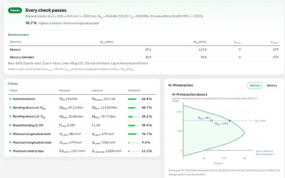
Column design calculator to Eurocode 2: braced, unbraced and slender columns
Design a rectangular RC column to EN 1992-1-1 with the free calculator: end restraints, loads, slenderness, second order moments and biaxial bending.
-
 Design guide
Load combinations and concrete cover to the Eurocodes: 6.10, 6.10a, 6.10b and nominal cover
How EN 1990 combines loads (Expressions 6.10, 6.10a, 6.10b and the SLS combinations) and how EN 1992-1-1 sets the nominal cover to the steel.
-
 Reference
From BS 8110 to Eurocode 2: what changes for reinforced concrete design
Moving from BS 8110 to EN 1992-1-1: concrete strength, partial factors, loads, bending, shear, deflection, cover and columns compared side by side.