
Design guide
Deflection and crack control to Eurocode 2: span/effective depth and Tables 7.2N and 7.3N
How Eurocode 2 checks deflection by the span to effective depth ratio (7.16a, 7.16b) and cracking by bar size and spacing, with worked examples.
- Reading time
- 4 minutes
- Standard
- EN 1992-1-1
- Clauses
- 7.3.2, 7.3.3, 7.4.2
- Calculator
- Slab
- Updated
On this page 3 sections
At the serviceability limit state a slab or beam must not sag too much, and its cracks must stay narrow enough not to spoil its look or let the steel corrode. EN 1992-1-1 lets both be checked without calculating deflections or crack widths directly: deflection by a limit on the span to effective depth ratio (7.4.2), and cracking by limits on the bar size or spacing (7.3.3).
Two members, worked below
- Slab, basic l/d
- 60.13
- lightly reinforced: Expression 7.16a
- Beam, basic l/d
- 16.13
- ρ close to ρ0: a tighter limit
- Beam steel stress
- 226.0 MPa
- σs under the quasi-permanent load
- Largest bar for cracking
- 23.9 mm
- from Table 7.2N at that stress
Deflection: the span to effective depth ratio
The limiting ratio depends on how heavily the section is reinforced. A lightly reinforced slab can be much more slender than a heavily reinforced beam, because its concrete is barely stressed. With as a reference ratio:
where is the tension steel ratio needed at mid-span, the compression steel ratio, and depends on the structural system (Table 7.4N): 1.0 for a simply supported span, 1.3 for an end span of a continuous member, 1.5 for an interior span and 0.4 for a cantilever.
The basic ratio is then adjusted:
- by (Expression 7.17), approximately , when more steel is provided than needed. The National Annex can cap this factor; the Sri Lanka annex caps it at 1.5;
- by for spans over 7 m carrying brittle partitions.
The whole check, from the steel ratio to the verdict:
- Steel ratio ρ = As,req / (b d) needed at mid-span
- Is ρ ≤ ρ0 = √fck / 1000?
Yes
- Basic ratio from Expression 7.16a
No
- Basic ratio from Expression 7.16b
- Times K for the structural system (Table 7.4N)
- Times 310/σs, about As,prov / As,req, within the annex's cap
- Times 7/leff for spans over 7 m with brittle partitions
- Is the actual leff / d within the limit?
Yes
- Deflection needs no further check
No
- Deepen the section, or add steel
- On to crack control
How steeply the limit falls with the steel ratio is easiest to see drawn out. Each curve below is Expression 7.16a and 7.16b as the calculator works them, for a simply supported span:
Basic span/depth ratio against the steel ratio
Simply supported spans, K = 1, from Expressions 7.16a and 7.16b. Lightly reinforced slabs may be far more slender than heavily reinforced beams, and a stronger concrete allows a little more.
- C25/30
- C30/37
- C40/50
Show the numbers
| Steel ratio ρ (%) | C25/30 | C30/37 | C40/50 |
|---|---|---|---|
| 0.20 | 59.1 | 73.7 | 105.3 |
| 0.35 | 26.2 | 31.3 | 42.8 |
| 0.50 | 18.5 | 20.5 | 25.8 |
| 0.65 | 16.8 | 17.9 | 20.2 |
| 0.80 | 15.7 | 16.6 | 18.5 |
| 0.95 | 14.9 | 15.7 | 17.3 |
| 1.10 | 14.4 | 15.1 | 16.5 |
| 1.25 | 14.0 | 14.6 | 15.8 |
| 1.40 | 13.7 | 14.2 | 15.3 |
| 1.50 | 13.5 | 14.0 | 15.0 |
For the single span slab of the slab guide, 175 mm thick, the steel ratio is low, so Expression 7.16a gives a generous limit:
Structural system factor — simply supported span
Reinforcement ratios
ρ ≤ ρ₀, so Expression (7.16a) applies.
Basic limiting span/effective depth
ρ = 0.227 % is far below the ρ = 0.5 % of the "lightly stressed" column of Table 7.4N (l/d = 20), and Expression (7.16a) rises steeply as ρ falls, so this limit is large. It follows the standard; for long or slender slabs a calculated check (7.4.3) is more reliable.
Steel stress modification
Span/effective depth check
For the 300 × 500 mm beam of the beam example, the ratio is close to and the check is tighter:
Reinforcement ratios
ρ > ρ₀, so Expression (7.16b) applies.
Basic limiting span/effective depth
Steel stress modification
Span/effective depth check
Cracking: limiting the crack width
Cracks are expected in reinforced concrete; the aim is to keep them narrow. Table 7.1N recommends a maximum crack width of 0.3 mm under the quasi-permanent load for most exposure classes, and 0.4 mm for dry, protected concrete (X0 and XC1). The National Annex can change these, and the calculator shows the value it uses. Clause 7.3.3 then gives two tables, so that the width does not have to be calculated:
- Table 7.2N: the largest bar diameter for a given steel stress;
- Table 7.3N: the largest bar spacing for a given steel stress.
Either one is enough. The steel stress is found for the cracked section under the quasi-permanent combination, so the beam's long-term (creep-adjusted) modular ratio is used:
Crack width limit
Effective modulus for long-term loading
Neutral axis of the cracked section
Elastic cracked section, tension concrete ignored.
Steel stress under the quasi-permanent load
EN 1992-1-1 §7.3.3(2), Eq. (7.6N)
Maximum bar diameter (Table 7.2N, adjusted by 7.6N)
φ*s from Table 7.2N for σs = 226.0 MPa and wmax = 0.3 mm, interpolated linearly in σs; hcr is the depth of the tension zone just before cracking.
Maximum bar spacing (Table 7.3N)
From Table 7.3N for σs = 226.0 MPa and wmax = 0.3 mm; s is the centre spacing of the tension bars.
Crack control check
Satisfied by the bar size (Table 7.2N); either table is sufficient.
The minimum steel for crack control (7.3.2) must also be present, so that the steel does not yield when the concrete first cracks:
EN 1992-1-1 §7.3.2(2), Eq. (7.2)
Minimum reinforcement for crack control
kc = 0.4 for the web in bending without axial force (7.2); k for h = 500 mm (≤ 300 mm: 1.0; ≥ 800 mm: 0.65). σs = fyk; fct,eff = fctm.
Thin slabs
Clause 7.3.3(1) exempts slabs up to 200 mm thick in bending without significant axial tension from these measures, provided the minimum steel is there and the bar spacing rules of 9.3 are met. The calculator applies this to the example slab:
Crack width limit
Crack control
The slab is 175 mm deep (≤ 200 mm), in bending without significant axial tension, and detailed to 9.3, so no specific crack-control measures are needed.
Points to remember
- Use the effective span and the effective depth to the centre of the tension steel.
- For a two-way slab, check the shorter span.
- The quasi-permanent load, not the ultimate load, sets the steel stress for cracking. For an office with , it is well below the ultimate load.
- If cracking fails, smaller bars at a closer spacing usually solve it, with the same steel area.
Open the slab calculator to try a thinner slab and watch the deflection check tighten.
Read next
-
 Calculator guide
Slab design calculator to Eurocode 2: one-way, continuous, cantilever and two-way slabs
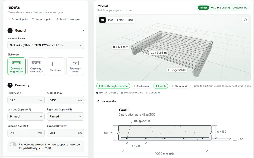
Design a reinforced concrete slab to EN 1992-1-1 with the free calculator: inputs, load arrangements, bending, shear, deflection and cracking.
-
 Design guide
Beam design to Eurocode 2: a worked example of bending
A simply supported RC beam designed for bending to EN 1992-1-1, step by step: loads, design moment, effective depth, lever arm, steel area and bars.
-
 Reference
The Sri Lanka National Annex to Eurocode 2: every value that differs from the recommended
Every value of NA to SLS EN 1992-1-1:2013 that differs from the CEN recommended values, from the 0.85 concrete factor to bar spacing and column steel.